Beam element: Define additional nodes for beam
elements
With this command elements of type 20 can be
assigned up to 3 additional nodes. The first additional node (third element
node) identifies the direction of the first main axis of the beam element. The forth
node is used as an eccentrically connection of the left end node and the fifth
node is used for an eccentrically connection of the right end node.
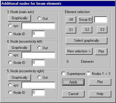
Following dialog shows the available options:

3. Node/ 4.
Node / 5. Node
Graphically: After pressing this button, the
node has to be selected by cursor. Node ID of the selected node is shown within
the related input field.
Xyz: Within the input field coordinates for a new
node to be generated can be given.
Node ID: The ID of an already defined node
can be entered.
Out: If this option is selected, the corresponding
node in the element definition is not changed.
Element
selection
All these
elements for which additional nodes should be defined have to be selected. Only
elements of type 20 are considered.
Apply
This
button assigns actual shown settings for selected elements
Plot
This
button causes a plot of all additional nodes for actually selected elements of
type 20. The main axis of beam elements is shown by a vector within center of
element gravity in direction of node 3. If option “Nodes 1->3” is set, a
colored line is plotted from nodes 1 to 3. The fourth element node will be
connected to the left end and the fifth element node will be connected to the
right element end by a colored line.