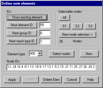
Define element: Define individual elements
graphically or numerically
This command lets you define individual macro
or finite elements where associated nodes are already defined. When deleting
elements an option must be set to keep the individual nodes. The dialog remains
active until it’s explicitly closed by „Cancel“.
Following dialog shows the available options:

IDs
Show existing element: Clicking the button, an existing element can be selected graphically;
whose parameters and node IDs are then shown within the dialog. This element
can be modified and replaced by pressing „Apply“. For example it’s possible to
add relevant nodes for a regular subdivision of a macro elements of type 105;
or with type 400 elements to mark intermediate nodes on circular edges with a –
sign, because this is not done automatically when reading type 400 elements
from AutoCAD.
Next element ID: This input field specifies the element ID to be used for a new
element. After each saving of an element, the currently largest element ID is
incremented by 1. This ID will also be set if the button is pressed. In case
the ID of an already existing element is given in the input field it will be
asked for overwriting.
Next group ID: This input field gives the group ID for new elements. If the button is
pressed the currently largest existing group ID incremented by one will be set.
Next mechanical Type ID: This input field gives the mechanical type ID for new elements. If the
button is pressed the currently largest existing mechanical type ID incremented
by one will be set.
Element
type
Element
type for new elements must be given. Only these types shown within the list box
can be graphically defined.
Node IDs
Internal
node IDs (indices of nodes) for the new element must be given according to the
order shown in Table 2.1. For element type x5 the last node of a curved edge
must be given a negative sign, while with type 105 corner nodes must be given a
negative sign (see chapter “Element types“)
New
If this
button is pressed, default values for the following available element ID will
be set.
Select
nodes
After
clicking this button the nodes of the new elements are to be selected
graphically. The IDs of selected nodes are shown within the dialog after
finishing one element. The number of nodes to be selected depends on the
element type. In case of a variable number (for example type 45, type 105 and
type 400 elements) the selection is ended by pressing the right mouse button.
Pressing the left mouse button does the node selection. In case the “-“ key is
pressed first, the selected node gets a minus sign (last node for spline curves
or intermediate nodes on edges for type 105 and type 400 elements). Selected
nodes are marked by a colored symbol; by pressing „d“ key, latest selected node
is made undone. In case there is a straight edge at elements of type x5, the
node at this edge must be given as „0“, this is done with key ‘0’ when doing
graphical selections. You can define new elements continuously until you press
the right mouse button. Each new element is shown graphically and can
immediately deleted by pressing button „Undo“.
Apply
This
button saves a newly numerically defined element and immediately it will be
colored displayed within the graphic window so its definition can be checked
and it may be immediately deleted pressing button “Undo”. In case an already
defined element should become overwritten it must explicitly be confirmed.
Undo
Pressing
this button causes latest defined element to be deleted.
Delete
elements
Clicking
this button, the dialog for deleting elements pops up.