Element load: Define and assign distributed
loads on elements
This command allows the definition of constant
or distributed element loads corresponding to the PATRAN interface. For each
element load up to 6 components may be given. Which components are given
defines a component flag (parameter ICOMP in PATRAN interface), for example
ICOMP = 13 (stands for the PATRAN flags 101000) means that the load consists of
a force component for the x- and z-direction.
For the PATRAN interface it’s possible to
define central or node related element loads. For central loads NC load values
must be specified, where NC means the number of active flags within ICOMP. For
node related loads node flags (parameter NODE in PATRAN interface) specifies to
which element nodes load values were assigned, for example NODE = 1234 (stands
for the PATRAN flags 11110000) means that load values are specified for the 4
corners of an element of type 42. The number of values to be provided is NN*NC
where NC is the number of activated flags in ICOMP and NN the number of
activated flags in NODE. Order is NC values for each node.
For the NASTRAN interface only a load set ID, a
type ID and load values in the input field for central load components are to
be given. With a type ID different types of loads are distinguished (see
chapter “Interfaces to FE-Programs“). All other given parameters in the dialog
(ICOMP, NODE, etc) are not used.
Each group of element loads is assigned a pair
of identifiers: one index and a load set ID. The load set ID can be identical
for different groups but each group must have its own index. When an existing
index is given within the corresponding input field all associated values of
that group can be displayed by pressing button “Show values”. These values can
then be modified, plotted or even deleted. Button „New index“ generates a new
index for the next load group.
Button „Apply“ saves specified values. Button
„Delete“ deletes previously saved values for a given index or range of indices.
Following Dialog shows the available options,
the dialog remains active until pressing button „Cancel“ ends it.
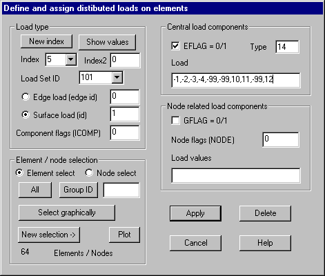
Load type
Index:
The index of an already defined or a new load group must be given. A given
number greater than the largest used number + 1 automatically reduces the
number to this value.
New index:
Next available index is set in the input field.
Index2:
For the buttons „Delete“ and „Plot“ an upper limit of a range of indices can be
given in this input field.
Show values:
Pressing this button, the stored values for the given index are displayed in
the dialog.
Load Set ID: An ID for the load set must be given. The list box shows all previously
used IDs.
Edge load:
For edge loads specify the ID of the associated element edge.
Surface loads: For surface loads on solid elements specify the surface ID (1-12) of
the solid element for which this load should be applied.
Component flags (ICOMP): In a number containing the digits 1-6 must be specified, for which
directions load components are given (for example 135 results to the flags
101010).
Central
load components
EFLAG: This flag has to be set if central load
components should be saved.
Type:
With a type ID different types of element loads may be distinguished (see
NASTRAN interface).
Load values:
A load value has to be given for each direction that is turned on in the flag
ICOMP. For NASTRAN, the number of load values depends on the given type ID; the
flags are not used (see NASTRAN interface).
Node
related load components:
GFLAG: This flag has to be set if node related load
components should be saved (not used with NASTRAN).
Node flags (NODE): In a number containing the digits 1-8 must be specified, for which element
nodes load values are given (for example 1234 results to the flags 11110000).
Load values: For each activated node in the flag NODE NC
load values must be given, where NC = number of activated components within
ICOMP.
Element /
node selection:
Alternatively
an element selection or a node selection may be specified. If a node selection
is given, all elements are searched for whose corner nodes are contained in the
given node selection. In case of solid elements, the surface of the solid is
searched whose corner nodes are contained in the node selection, the ID of this
surface is used for the interface.