Information: General information about the
assignments, node coordinates, etc.
This command
shows several kinds of information (element ID’s, group ID’s etc.) for selected
elements. By pressing “Element selection” a new selection can be defined
several times, from which the assignments are displayed.
Following dialog
shows the available options:
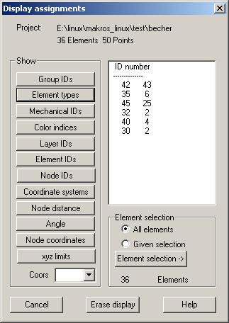
Show
Group IDs, Element types, Mechanical IDs, Color indices, Layer IDs: With these buttons there will be
shown the existing ID’s within the structure together with the number of
assignments.
Element IDs: The distribution of element ID’s will be shown. First and last ID shows
each continuous range of ID’s.
Node ID:
The distribution of node ID’s will be shown. First and last ID shows each
continuous range of ID’s.
Coordinate systems: The ID and type of currently defined local coordinate systems are
shown.
Node distance: After pressing this button 2 nodes must be repeatedly selected within
the graphics window. The distance between these nodes will be calculated and
shown.
Angle:
After pressing this button 3 nodes must be repeatedly selected within the
graphics window. The angle within the first node will be shown.
Node coordinates: After pressing this button the nodes whose coordinates should be
displayed have to be selected graphically. If a local coordinate system is
selected in the list box the coordinates are shown in reference to this coordinate
system.
xyz-limits:
Maximal and minimal x,y- and z-coordinates are shown. If a local coordinate
system is selected in the list box the coordinate limits are shown in reference
this coordinate system.