Intersection: Calculate nodes on the
intersection curve of two regular surfaces
This command calculates nodes on an
intersection curve of two regular surfaces. The following types of surfaces are
supported: Plane, circular cylinder, sphere, cone and torus.
The command is used to produce individual nodes
to define macro elements, or to move nodes created by the subdivision of macro
elements, onto a regular surface to get a smoother structure. The definition is
done by first creating additional nodes on one surface then move these nodes
along a given direction onto the other surface. For example moving nodes on the
surface of a circular cylinder along the direction of the cylinder axis onto a
torus, will calculate nodes on the intersection curve of this circular cylinder
with the torroidal surface. You can choose to create additional nodes or to
move existing ones. Creating additional nodes will assign node elements
(element type 1) to these nodes because only nodes of existing elements can be
saved.
After specifying the parameters within the
corresponding dialog the nodes to be moved onto the regular surface have to be
selected. Button "Apply" causes the calculation to be done. Multiple
selections can be specified. Pressing "Cancel" closes the dialog.
In case no intersection can be found, for
example because the defining nodes of a plane surface are placed on a straight
line or because there are no intersections within the given direction, an error
message is produced. Otherwise the number of calculated intersections is shown.
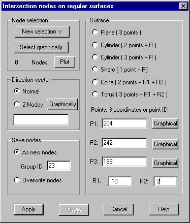
Following dialog shows the available options:

Surface
Plane: 3
nodes defining the plane must be provided
Circular cylinder: 2 nodes defining the axis respectively 3 nodes defining a plane
perpendicular to the cylinder axis and the radius of the cylinder must be
provided.
Sphere:
Center and radius must be provided
Cone: 2
nodes on the cone axis and the radii of the cone at these 2 nodes must be
provided
Torus: 3
nodes within the plane of the torus and the 2 radii must be provided
Points P1-P3: Coordinates (x,y,z) of the related points or an existing node ID must
be provided
By
pressing „Graphical“ the corresponding node is to be selected within OpenGL
window. The IDs of these selected nodes are entered within input fields.
R1,R2: If
needed by the chosen surface, the radii must be provided
Direction
vector
3 vector
components of the desired direction of intersection or the external IDs of 2
existing nodes must be provided. In case of 2 IDs, the direction vector is
build from the coordinate difference between these nodes. The direction can be
arbitrarily, except with toroidal surfaces where the direction must be parallel
or perpendicular to the toroidal plane. Clicking „Graphically“ causes the
graphical selection of 2 nodes, defining the direction for intersection. In
case option „Normal“ is marked, the normal vector of the surface is used as a
direction vector, no additional input is necessary.
Save nodes
As new nodes: The calculated intersection nodes are saved as new nodes together with
an associated node element. Within the input field "Group ID" these
elements can be assigned a group ID.
Overwrite nodes: The coordinates calculated by the intersection replace the coordinates
of the original nodes, i.e. the original nodes are moved onto the regular
surface.
Node
selection
Within
the corresponding dialog nodes can be selected at multiple times. Nodes can
also be selected graphically.
Undo
Pressing
this button will delete the latest created nodes.