Plot: Plot elements
The command plots selected elements within one
or distinct AutoCAD layers respectively display lists. It's possible to
distinguish between different kinds of plots ranging from wire frame to surface
plots. In all cases curved edges are approximated by polylines where additional
nodes between vertices are automatically calculated to smooth the plot. This
can be suppressed when transferring elements to AutoCAD. It should be
suppressed when these elements are intended to be read back (after a
modification within AutoCAD) by MAKROS.
Option „Edges only“ draws the edges of the
elements as wire frames. Surface elements will be drawn as closed polylines.
When transferred to AutoCAD, solids of type 8x are drawn with 9 edges within
one polyline, the remaining 3 vertical edges are drawn as separate polylines.
All these elements can be re-read with the command Read AutoCAD.
Option „Surface mesh“ plots all selected
elements as an AutoCAD mesh. This option can only be used during a graphical
plot within AutoCAD. It is only implemented for elements of type 30 and 40.
This kind of plotting has the advantage that all elements are corrected when
moving common nodes. This isn't the case in edge plot mode where all relevant
elements are drawn as separate polylines. Surface meshes can be read again as a
macro or FE model. In case of a large structure it should be divided by
suitable element selections into several plots.
Option „Sharp edges only“ plots edges where the
angle between the normal vectors of the adjacent surfaces is larger than the
given value. Only these edges and the edges with only one adjacent surface are
plotted. This way it's easy to detect gaps within the structure. Solid
structures are represented only by their outer surfaces. The angle must be
provided in degrees.
Option „Plot of surfaces“ plots all elements in
AutoCAD as a polygon mesh. Solid structures are represented only by their outer
surfaces. With this kind of plot AutoCAD rendering can be used for hidden line
removal or shading. Elements plotted this way cannot be read back with the
command Read AutoCAD. Graphical
outputs within an OpenGL window automatically suppresses hidden lines and
surfaces, curved surfaces are approximated by triangles. It’s also possible to
shade the structure using a specified light source.
Pressing button “Plot” starts the graphical
output. By pressing button „Erase Display“ the graphics window will be erased
(including all OpenGL display lists). Button „Copy“ causes a new window to be
opened with a copy of the existing window so it will be possible to compare
multiple views of the structure.
Following Dialog shows the available options:
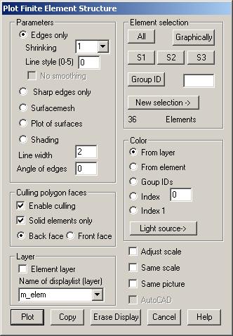
Parameters
Edges only: Edges of the elements are plotted as
polylines. With „No smoothing” set, no additional nodes on curved edges will be
generated when transferring the elements to AutoCAD.
Shrinking:
Factors < 1.0 reduces elements in size when plotted by shrinking them
towards there center.
Line style:
When plotting edges a line style (0-5) used for all edges can be set.
Sharp edges only: Only sharp edges of the structure are plotted. The max. angle between
normal vectors must be given.
Surface mesh: Elements are plotted as AutoCAD 3D mesh (only
for types 30 and 40 and option “AutoCAD”).
Plot of surfaces: The outer surface of the element structure is
approximated by triangles and hidden line removal is done. An angle of sharp
edges can also be given.
Shading:
One or more light sources (see Light source) may be witched on to produce a shaded image.
Line width:
In the input field, the width of the lines in pixels can be given.
Angle on edges: If an angle > 0 is given when using surface or shaded plots only
those edges between surfaces with an angle between their normal vectors greater
than this value will be plotted. This value must also be set when using “sharp
edge plots”.
Culling
polygon faces
Enable culling: If this option is marked culling facility of OpenGL is switched on, so
that only faces with normal vector directed to the camera position (option back
faces) or opposite (option front faces) are plotted.
Solid elements only: If this option is also marked, culling is only applied to faces that
belong to solid elements.
Layer
Element layer: With this option set, all elements will be
drawn in different layers respectively display lists. There must have been made
an association of layer numbers and layer names to the elements. OpenGL
graphics use one display list for each layer.
New layer: With this option set, new names for layers
will be created and used when transferring the structure to AutoCAD.
Using new
layer names is importing, when transferring elements to AutoCAD, because
existing entities of the used layers will at first be erased. With OpenGL,
using different display lists makes it possible to turn the plot of parts of
the structure on and off.
Element
selection
Only
elements contained in the selection are plotted.
Color
From layer:
The color indices associated with the layers will be used.
From element: Previously assigned element color is used.
Group IDs:
The elements group ID will be used as a color index.
Index:
All elements are plotted with this index.
Light source: Pressing this button, a dialog pops up where a light source can be
specified.
Adjust
scale
With this
option set scaling and center of the image will be automatically adapted for
the next plot based on the size of the current graphics window. Otherwise new
scaling is only performed when changing the current element selection.
Same scale
Each time
a new element selection is drawn, the reference point and scale factor are
newly calculated. With this option set the old view is used instead. So
different parts of the structure can be superimposed with different colors on
different display lists.
Same
picture
By
default all display lists respectively used AutoCAD layers are erased before
plotting. With this option set erasing won’t be done. When using OpenGL another
display list must be specified, a previously used display list can’t be
extended.
AutoCAD
With this
option active selected elements are transferred to and plotted within AutoCAD.
Otherwise the OpenGL graphics window is used. This option is only available
after starting MAKROS from within AutoCAD.