Read AutoCAD data: Read elements from AutoCAD or
DXF-Files
With this command, elements can be read
directly from a distinct or from multiple AutoCAD layers or from a DXF-File.
Chapter “Definition of macro elements within
AutoCAD” describes which types of AutoCAD entities can be read. Only individual
entities can be read, nested entities such as blocks and regions or polylines
composed out of lines and arcs must be divided into individual entity’s first,
using AutoCAD command “xplode”. If some entities cannot be interpreted as makro
elements (e.g. only two corner nodes with a curved surface element), these
entities are left out. Read elements will be appended to the prior read
structure, except option "Delete old elements" is selected. After
invocation of the command the following dialog box pops up. After checking and
setting up the proper options the button "Read" will start reading.
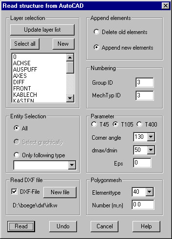
Layer
selection:
The list
shows all available layers currently defined within AutoCAD or contained in the
DXF file. Select the layers to read entities from. One or more layers can be
selected. The button „Select all“ selects all layers and the button „New“
deselects all layers. With button „Update layer list“ the available layers are
new checked, this could be necessary after new AutoCAD layers have been
generated or a new DXF file is selected.
The
AutoCAD layers are continuously numbered and this number is stored as a layer
ID with the elements.
Entity
selection
All: All AutoCAD entities of the given layers will be read and converted to
macro elements. The interpretation of the entities is discussed within chapter
“Definition of macro elements within AutoCAD”.
Select graphically: Only these entities will be read, which are
contained within a following selection with AutoCAD commands. Only elements
from one marked layer can be selected. Pressing Return ends selections. Start
the AutoCAD selection after pressing button „Read“ and after you have confirmed
that you will select graphically in a pop up dialog.
Only following type: If this option is selected, an entity type (POLYLINE, LINE, CIRCLE,
ARC, SOLID, 3DFACE, TRACE, POINT) must be selected in the list. In this case
only entities of the given type are read from the selected layers.
Read DXF-File
If the option „DXF-File“ is marked, the title
of a DXF-File must be selected in a file selection window. The layers contained
in the file are shown in the layer list. You can select individual layers and
entity types that should be read from the file. Button „New file“ shows a file
selection window where a new file can be selected.
Append
elements
Delete old elements: All previously read elements will be deleted.
Append new elements: Newly read elements are appended to previously read elements.
Numbering
Group ID: You can specify a group ID for the new
elements. Default is the highest group ID + 1.
Mechanical type ID: You can specify a mechanical type ID for the
new elements. Default is the highest type ID + 1.
Parameter
T105:
With this option selected, closed polylines with more than 4 corner nodes
(vertices with an inner angle less than the given value) are stored as type 105
elements.
T400:
With this option selected, closed polylines with more than 5 vertices are
stored as type 400 elements with straight edges. If some edges should be
circular, the intermediated nodes on these edges must later be marked with a –
sign using command “Element definition”.
T45: With
this option selected, polylines with more than 4 corner nodes (vertices with an
inner angle less than the given value) are stored as type 45 elements, where
only the 3 smallest corners and the first are considered as element corners.
Corner angle: Within this input field you may enter an angle value for the
interpretation of polylines. All polyline vertices with inner angles lower than
this value are considered as element corner nodes while remaining vertices in
this case are considered as intermediate nodes on element edges. This is not
applied by elements that are defined using successive polyline vertices with
equal coordinates (double vertices).
Dmax/dmin:
This input field may contain the ratio m. All vertices within a distance lower
than dmax/m will be considered as double vertices. dmax stands for the maximum
distance between 2 vertices.
Eps: After
reading from AutoCAD all nodes with distance lower than this value (eps) will
be merged into a single node. If no value > 0 is given, the value of eps
will be set automatically in relation to the smallest edge length of all
elements. Providing a value for eps would be useful to prevent merging of
closely related nodes.
Polygon
mesh
Element type: For polygon meshes it is possible to generate elements of type 40, 42
and 45. Default is saving each mesh as an individual 4-node element. With
element type 42 2*2 neighbored meshes are saved as an element with one
intermediate node on the edges. For element type 45 4*4 meshes are converted as
an element with 3 intermediate nodes on the edges.
Number:
Within this field it is possible to specify the number of elements to be
generated for x and y direction. This means that not all edges of the polygon
mesh will be used for element generation. If, for example, the polygon mesh
consists of 128 segments in one direction and only every second edge should be
used for generating type 45 elements, the number should be given as 16.