Reference Point: Define reference points for
division of macro elements
This command allows defining reference points
on edges of macro elements that shall become finite element nodes when the
macro element is subdivided. The reference points are assigned to edges of
macro elements; the corner nodes of these edges must graphically be selected.
For each edge with reference points, the number of those points, their relative
position and the number of intermediate nodes that should be generated between
these points is stored. A maximum of four reference points may be given for one
edge. The number of intermediate nodes between the reference points may also be
defined using the command Division where each part of edges with
reference points is divided individually.
The definition of reference points is saved
within the file project.mut.
In most cases following steps may be useful
(see demo “referencepoint.dem”).
1) Define
the position of reference points, without defining the number of intermediate
nodes.
2) Divide
all edges using the command Division.
3) Do a
graphical test of the subdivision of some elements using command Subdivision and the option “Test individual elements”.
4) If
there are triangular finite elements are generated for some macro elements,
correct the number of intermediate nodes for some parts of edges with reference
points by using the option “Show # of intermediate nodes / Redefine”.
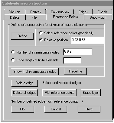
Following dialog shows the available options:

Define
reference points for division of macro elements
Select reference points graphically: If this option is marked, after selecting the
end nodes of an element edge the reference nodes on that edge have to be
selected graphically. Selection of reference nodes is finished with the right
mouse button, then the next edge may be selected or finish selection with right
mouse button. The reference points to be selected must lie within a small
tolerance on the edge.
Relative position: Using this option, the relative position (0 < s < 1) for up to 4
reference points must be given in the corresponding input field.
Number of intermediate nodes: Using this option, for each part of the edge
the number of intermediate nodes that should be generated when the edge is
subdivided must be given in the input field. Missing values are set to 0. The
number of intermediate nodes may be omitted when it is later determined by
using command Division.
Edge length of finite elements: Using this option, the maximal length of
finite element edges must be given in the input field. The parts of the edge
are then subdivided as with command Division.
Define:
After clicking this button, edges with reference points have to be selected
graphically by selecting the end nodes of the edge. Selection is ended with the
right mouse button, eventually also the reference nodes on the edges must also
be selected graphically if option “select reference points graphically” is
marked. If there are already reference points defined for an edge, these are
replaced by the new definition.
Show number of intermediate nodes / Redefine: Clicking the first button, an edge
must be selected graphically by selecting the end nodes, then the relative
position of reference points on this edge and the number of intermediate nodes
for the parts of the edge is shown in the corresponding input fields. After
that, the number of intermediate nodes may be altered in the input field and be
saved for the latest selected edge by clicking the button “Redefine”.
Delete edge
After
clicking this button, the end nodes of the edges must be graphically selected
that reference points should be deleted. Selection is ended with the right
mouse button.
Delete all
edges
Clicking
this button, all defined reference points are deleted.
Plot
reference points
Clicking
this button, all edges that have reference points are plotted together with the
reference points and the intermediate nodes on the parts of the edge.
Erase layer
Clicking
this button, the layers on which the reference points and the intermediate
nodes are plotted on are erased.
Plot
Clicking
this button, the intermediate nodes on all element edges are plotted.