Smoothing: Shift nodes on a regular surface
With this
command selected nodes can be moved to regular surfaces to smooth the
structure. Smoothing especially will be necessary after subdivision of macro
elements with curved surfaces where these curves are located on such regular
surfaces. The calculation of additional internal nodes during this subdivision
is based on C0-Coons interpolation, which executes linear transition
between opposite edges. Especially for nodes on spherical or toroidal surfaces
the calculated nodes may more or less differ from the regular surface.
The regular
surface must be defined within a local coordinate system. In case no local
coordinate system is given the global system is used. After the definition of
the surface all these nodes have to be selected which are to be moved onto this
surface. With option “Maximum distance” a maximum distance may be specified.
Nodes with distances from the surface greater than this value aren’t moved.
Moving is done perpendicular to the specified regular surface.
Moving of nodes
can also be done by command Intersection, which does a translation of nodes along a vector and so an
intersection of 2 regular surfaces can be achieved.
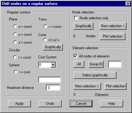
Following dialog
shows the available options:

Regular
surface
Plane:
Any of x,y,z values can be set as a constant value in respect to a given
coordinate system i.e. only the value in this direction is changed to the given
value. The relevant value must be provided in the input field.
Circular cylinder: Radius must be given in the input field. Z-axis of the given
coordinate system will be chosen as the axis of the cylinder.
Sphere:
The radius of the sphere must be given in the input field. Basis of the given
coordinate system will be chosen as the center of the sphere.
Torus:
The radius of the toroidal surface must be given in the input field. Nodes P1
and P2 of the given coordinate system define the radius of the torus. This
coordinate system must be defined as a toroidal system.
Cone: Two
ID’s of nodes lying on the cone surface must be given. If button “Graphically”
is pressed, the 2 nodes can be selected graphically. The z-axis of the selected
coordinate system will be used as the cone axis. The displacement of the nodes
is perpendicular to the cone surface.
Coor System:
The ID of a previously defined coordinate
system must be given. The list box shows all currently available systems. ID 0
is for global coordinate system.
Input field: Parameters (for example radius, node ID’s) must be given within this
input field.
Maximum distance: Maximum value for the distance a node can be moved may be given.
Node
selection / element selection
Select
nodes to be translated or select elements where all nodes of selected elements
are considered.
Undo
Pressing
this button, the latest displacement is made undone.