Surface loads: Define distributed loads on
surface elements, calculate statically equivalent forces
The command allows do define constant or
variably distributed loads on a plane or a cylindrical surface whereby the
distributed load is immediately converted to statically equivalent forces on
the corner nodes of the loaded elements.
The area and the direction of the distributed
load are defined in a local coordinate system that is determined by 3 element
nodes. The line from the first to the second node gives the local x-axis. The
given 3 nodes also define the maximal expansion of the load area; it must
completely be contained within the limits of the local coordinates given by the
3 points.
At first, all elements or surfaces of solid
elements are determined, that lie on the plane and within the expansion of the
local coordinate system, only the corner nodes of these elements respectively
element surfaces are considered.
Four types of surface loads are distinguished:
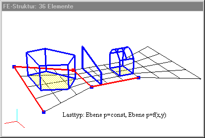
Plane, p =
constant
With this option, the loaded area may be a
convex polygon of up to 8 points. Only constant load distribution is allowed
(see following picture).
Plane, p = f (x,
y)
With this option, the loaded area must be
rectangular and parallel to the axis of the local coordinate system. All loaded
elements must also be rectangular and parallel to the axis of the local
coordinate system. The distributed load may be variable in both directions (see
following picture).

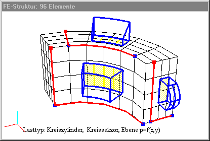
Section of
a circle
With this option, a rectangular section of a
circle is loaded. Additional to the 3 reference nodes the ID of a defined
cylindrical coordinate system must be given. All edges of loaded elements must
be parallel to the axis of the given cylindrical system. The distributed load
may be variable in both directions (see following picture).
Cylindrical
surface
With this option, a rectangular section of a
cylindrical surface is loaded. Additional to the 3 reference nodes the ID of a
defined cylindrical coordinate system must be given. All edges of loaded
elements must be parallel to the axis of the given cylindrical system. The
distributed load may be variable in both directions (see following picture).

Each defined surface load is identified by 2
IDs, an index and a load set ID. The load set ID may be the same for different
surface loads, but each surface load has a unique index. Pressing button “New
index” gets the next unused index. Loads defined with command Element loads and Surface pressure are stored in the same data structure and use the same continuous range
of indices. If the index of a stored surface load is given in the corresponding
input field, with button “Show values” the stored values are displayed in the
dialog box. These values may be plotted, deleted or modified. With button
“Apply” the given values in the dialog are stored and the statically equivalent
node forces are calculated and stored in the data structure. With button
“Delete” stored values may be deleted.
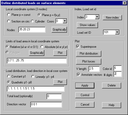
Following dialog shows the available options:

Local
coordinate system (3 nodes)
Plane (p = constant): A rectangular or polygonal bounded area with a constant load can be
defined.
Plane (p = f (x, y)): A rectangular area with a variably distributed load can be defined.
Edges of the load area and of the elements must be parallel to the axis of the
local coordinate system.
Section of a circle: A rectangular area of a circle with a variably distributed load can be
defined. Additionally to the 3 nodes, the ID of a defined cylindrical
coordinate system must be given; the list box shows all defined coordinate
systems. Edges of the loaded area and of the elements must be parallel to the
axis of the cylindrical coordinate system.
Cylindrical surface: A rectangular area of a cylindrical surface with variably distributed
loads can be defined. Additionally to the 3 nodes, the ID of a defined
cylindrical coordinate system must be given; the list box shows all defined
coordinate systems. Edges of the loaded area and of the elements must be
parallel to the axis of the cylindrical coordinate system.
Nodes:
The IDs of 3 nodes to define the local coordinate system must be given. After
pressing button “Graphically” the 3 nodes can be selected graphically.
Limits of
load area in the local coordinate system.
Relative (ul, ur, vl, vr): The left and right limits of the rectangular
load area must be given relative to the length of the axis of the local
coordinate system (0 £ u, v £ 1). The left and right limits may
be the same to define a line or point load.
Absolute (xl, xr, yl, yr): The left and right limits of the rectangular
load area must be given in coordinates of the local coordinate system.
Polygon:
The (u, v) coordinates of up to 8 vertices of a polygon must be given relative
to the length of the axis of the local coordinate system (0 £ u, v £ 1). The load area must be convex.
This option is only available for a local coordinate system of type “Plane, p =
constant”.
Graphically:
After pressing this button, left and right limits of a rectangular area
respectively of up to 8 vertices of a polygonal area can be selected
graphically. The relative coordinates of the selected points are shown in the
input field.
Plot:
Pressing this button, the expansion of the loaded area is shown graphically.
Load
distribution, load direction in the local coordinate system.
Constant:
The value of a constant load distribution must be given.
Linearly:
The load values at the 4 corners in the counter clockwise order must be given.
Quadratic:
Additionally to the 4 values by linearly distribution 4 load values at the
means of the 4 edges of the rectangular load area must be given.
Plot:
Pressing this button, the load distribution is shown graphically.
Total load:
If a value > 0 is given in the input field, the calculated forces are scaled
so that the amount of the resultant is equal to this value.
Direction vector: The direction of the calculated force vectors must be given relative
to the local coordinate system.
Index, Load
set ID.
Index:
The index of a new or already defined load group must be given. The list box
shows all previously used indices for this kind of distributed loads. For the
buttons “Plot” and “Delete” 2 indices of a range of indices may be given.
New index:
Pressing this button the next unused index is shown in the input field for a
new load group.
Show values:
If the index of an already defined load group is given, the stored values of
this group are displayed in the dialog after pressing this button.
Load set ID:
A load set ID must be given for a new load group. The list box shows all
previously used load set IDs.
Plot
Superimpose:
If this option is marked, a new display list is used for plotting.
Plot load distribution: For the given index or range of indices the following is plotted:
reference nodes and axis of a local coordinate system, load area and load
distribution.
Plot forces:
For the given index or range of indices the calculated statically equivalent
forces are plotted.
Vlength:
The plotted length of the largest vector respectively the maximal height for
the load distribution must be given.
Color index:
The color index for the plot must be given.
Annotate vectors: If this option is set, the vectors are labeled with the amount of the
force vector.
Digits:
If the vectors are to be labeled, the number of digits after the decimal point
must be given.
Control
Pressing
this button, the resultant of the force vectors is calculated. The components
of the resultant and its position relative to the local coordinate system are
displayed in the protocol window. The resultant is also graphically displayed.
Apply
The given
values are stored in the internal data structure; the statically equivalent
node forces are also calculated and stored. If there are already values stored under
the given index, it is asked for overwriting.
Delete
All
stored values for the given index or range of indices are deleted.