“Element definition” dialog
Use this dialog to define macro
elements graphically. The nodes to be used must have been created before. It
can freely be switched between the dialogs “Node definition” and “Element definition”. Newly defined macro elements are assigned to the active SURF element.
After clicking the button “Define elements”, the nodes of the new elements must be
selected graphically. The number of nodes to be selected depends on the type of
macro element. For element types with a variable number of nodes ( types 35,
45, 105, 400), node selection is finished by clicking the right mouse button.
For the selection of nodes the left mouse button is used, if the “–“ key is
pressed before, the ID of the selected node will get a “–“ sign ( last node of
each edge of element types 35, 45 and all intermediately nodes on edges of
element types 105, 400). Selected nodes are immediately marked with a colored
symbol, pressing d key a wrongly selected node is removed. If with element type
35 or 45 an edge is straight, press 0 key for the intermediate node of this
edge. Each newly defined macro element is plotted immediately. Macro elements
may be defined repeatedly, clicking button “Undo”;
the last defined macro element is removed. Finish the definition of new elements
by pressing right mouse button.
After all macro elements of the
active SURF element have been defined, nodes of the SURF element not used
should be removed clicking button “Remove not used nodes”.
The following dialog shows the
available options:
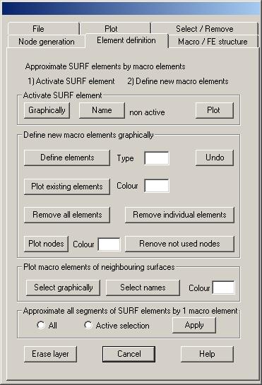
Activate SURF element
Graphically: Clicking this button, the names of
the actually displayed SURF elements are plotted with an additional symbol.
Using the cursor select the symbol of the SURF element to be activated. The
newly activated SURF element is displayed together with the bounding CONS
elements.
Name: Clicking this button, a text window pops up
with the names of all SURF elements. Mark the name of the SURF element to be
activated and click the “OK” button of the text window.
Plot: Clicking this button, the active SURF element
and the bounding CONS elements are newly plotted.
Define new macro elements graphically
Define element: After clicking this button new
macro elements are defined graphically. The type of the new macro elements must
be given in the input field, possible types are 30, 32, 35, 40, 42, 45, 105,
400. Definition of elements is done as with the command “Element definition” (see chapter “Commands to generate
new nodes and elements”).
Undo: Clicking this button, the last defined macro
element is removed.
Plot macro elements: Clicking this button all defined
macro elements of the active SURF element are newly plotted, where corner nodes
are marked with the symbol “E” and intermediate nodes on edges with the symbol
“Z”.
Remove all macro elements: Clicking this button, all macro
elements of the active SURF element are removed.
Remove individual elements: After clicking this button, macro
elements to be removed must be selected graphically.
Remove not used nodes: Clicking this button, all nodes of
the active SURF element that are not used for element definition are removed.
Plot macro elements of neighbouring surfaces
Select graphically: After clicking this button, select
graphically all neighbouring SURF elements of which the macro elements should
be plotted. Nodes of the macro elements are marked by the symbols “E” for edge
nodes and “Z” for intermediate nodes on edges. The colour index to plot the
macro elements must be given. Symbols are plotted using font index 2.
Select names: Clicking this button neighbouring
SURF elements are selected by name in a text window.
Approximate all segments of SURF elements by
one macro element
Clicking button “Apply”,
all segments of the SURF elements that are contained in the actual SURF element
selection are approximated by one macro element of type 42. This option is
useful when no boundary curves are given for the surfaces. To define a SURF
selection, use dialog “Selection
/ Remove”.