“Define nodes” dialog
Using this dialog, nodes for the definition of
macro elements are created. Nodes are assigned to SURF elements, so one SURF
element must always be active. If a boundary curve exists for the active SURF
element, this is plotted using a different colour.
Following dialog shows the available options:
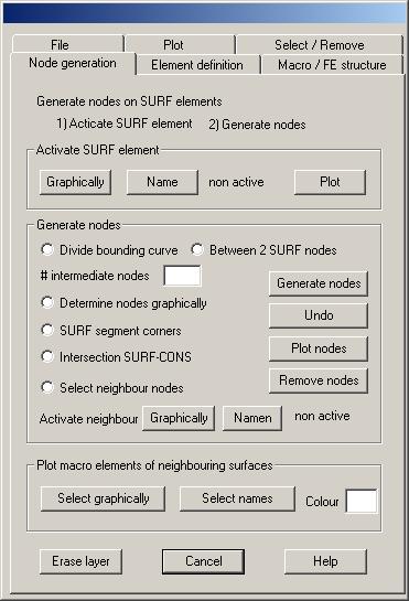
Activate SURF element
Graphically: Clicking this button, the names of
the actually displayed SURF elements are plotted with an additional symbol. Use
the cursor to select the symbol of the SURF element to be activated. The newly
activated SURF element is displayed together with the bounding CONS elements.
Name: Clicking this button, a text window pops up
with the names of all SURF elements. Mark the name of the SURF element to be
activated with cursor and click the OK button of the text window.
Plot: Clicking this button, the active SURF element
and the bounding CONS elements are newly plotted.
Generate nodes
Following options may be used to generate new
nodes on the active SURF element:
Divide bounding curve: Using this option, nodes are
generated on the bounding curve of the SURF element. Nodes are generated at the
end points of all CONS segments. If the number of intermediate nodes given is
greater than 1, this number of nodes is generated additionally in the inner of
the CONS segments.
Between 2 SURF nodes: With this option, two existing
nodes of the active SURF element are repeatedly selected graphically; then, on
the line between these two nodes, m intermediate nodes are generated, where m
is the number given in the input field.
Number of intermediate nodes: In the input field the number of
intermediate nodes to be used with the two options above must be given.
Determine intermediate nodes
graphically:
With this option, you first select graphically two existing nodes of the active
SURF element. A line between these two nodes is plotted, then, using left mouse
button, you repeatedly mark the location of the new nodes to be generated on
this line. Clicking right mouse button finishes the generation of new nodes on
the active line. Then, the end nodes of a new line may be selected until the
right mouse button is pressed twice.
SURF segment corners: With this option, one node is generated
at the corners of all SURF segments.
Intersection SURF-CONS: With this option, one node is
generated at the intersection of the edges of SURF segments and the bounding
curves of the surface (CONS elements).
Select neighbour nodes: This option enables generating
nodes on the bounding curve of the active SURF element that have nearly the
same coordinates as existing nodes of neighbour SURF elements. First a
neighbour SURF element must be activated by clicking the button “Graphically” or “Name”;
all defined macro elements of this SURF element are plotted, where the nodes of
these elements are marked by the symbol “E” for corner nodes and “Z” for
intermediate nodes on edges. These nodes then are graphically selectable.
Selecting one of these nodes by using left mouse button, a new node on the
bounding curve of the active SURF element is generated, with coordinates as
closely as possibly as the selected node. This requires the distance of the
selected node and the bounding curve of the active SURF element to be less than
a given tolerance.
Graphically: Click this button to activate a
neighbour SURF element graphically.
Name: Click this button to activate a neighbour
SURF element by name.
Generate nodes: After having chosen how to
generate new nodes, click this button to start the operation. Newly generated
nodes are immediately plotted.
Undo: Clicking this button, the latest generated
nodes are removed.
Plot nodes: Clicking this button, all nodes of
the active SURF element are newly plotted.
Remove nodes: Clicking this button, all nodes of
the active SURF element, which have not been used for the definition of macro
elements, are removed.
Plot macro elements of neighbouring surfaces
Select graphically: After clicking this button select
graphically all neighbouring SURF elements of which the macro elements should
be plotted. Nodes of the macro elements are marked by the symbols “E” for
corner nodes and “Z” for intermediate nodes on edges. The colour index to plot
the macro elements must be given. Symbols are plotted using font index 2.
Select names: Clicking this button, neighbouring
SURF elements are selected by name in a text window.